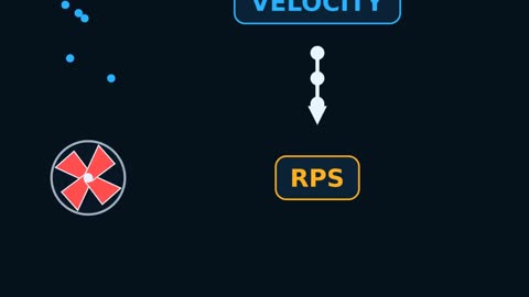
The PLT: the Spinner up close
Lesson Summary
A small propeller that rotates at a speed proportional to the fluid velocity, identifying which layer is producing and how much.
This lesson is part of the Formation Evaluation track and lasts 3:01 minutes. Watch the video first, then review the key points and test your understanding with the questions below.
Key Points
- 1Rotations per second (RPS) is proportional to velocity
- 2Record downhole and uphole at different speeds for calibration
Written Lesson
Why do we need production logging?
When a well produces from multiple layers or a long perforated interval, surface meters only show the total. Important questions are more specific: Which layer produces the most? Where is the water coming from? Is any layer not producing at all? To answer these, we run a Production Logging Tool (PLT), which includes several sensors: a flowmeter (Spinner), pressure, temperature, density or water-cut sensors, and sometimes phase identification sensors.
How does the Spinner work?
The Spinner is a small propeller on an axis that rotates as fluid passes around it; its rotation speed increases with the fluid velocity relative to the tool. Rotation is measured in rotations per second (RPS). Crucially, the propeller measures the relative velocity between the fluid and the tool, and the tool itself is moving on the cable. If we move down against an upward flow, the spinner rotates faster; if we move up with the flow, it rotates slower.
There is also a Threshold: a minimum velocity must be exceeded for the propeller to start rotating due to mechanical friction; this varies by spinner type and fluid viscosity.
In-Situ Calibration
The relationship between RPS and velocity changes with fluid properties; therefore, we do not rely solely on lab calibration but calibrate in the well itself. We record multiple down and up passes at different cable speeds, then plot RPS versus cable speed for each depth. The resulting line allows us to find the cable speed at which rotation stops, which tells us the fluid velocity.
RPS ≈ m × (V(tool) + V(fluid)) (tool moving down, upward flow)
Calculated Example: In a zone above all perforations: at a down-run speed of 30 ft/min the reading was 6.0 RPS, and at 90 ft/min it was 12.0 RPS. The slope m = (12.0 − 6.0) ÷ (90 − 30) = 0.1 RPS per ft/min. Substituting: 6.0 = 0.1 × (30 + Vf), which means 30 + Vf = 60, so the apparent fluid velocity Vf = 30 ft/min. To check: 0.1 × (90 + 30) = 12.0 RPS. (Threshold was ignored in this example for simplicity.)
From Velocity to Rate
The spinner measures velocity approximately at the center of the pipe, while the average velocity across the cross-section is lower because velocity decreases near the wall. Therefore, we multiply by a correction factor; a common value in turbulent flow is around 0.83, and lower values are used in laminar flow.
q (bbl/d) = V(mean) (ft/min) × A (ft²) × 1,440 ÷ 5.615
Calculated Example: Inside Casing with an ID of 6.184 in: Area 0.7854 × (6.184 ÷ 12)² ≈ 0.2086 ft². Average velocity ≈ 0.83 × 30 ≈ 24.9 ft/min. Rate ≈ 24.9 × 0.2086 × 1,440 ÷ 5.615 ≈ 1,332 bbl/d, in wellbore units at downhole conditions, not surface conditions.
Reading the Profile (Profile)
We repeat the calculation at multiple depths: above the perforations, between each layer, and below the deepest one where the flow should be zero. The difference in rate between two points equals the production from the layer between them.
Calculated Example: Above all perforations 1,332 bbl/d, between the upper and lower layer 800 bbl/d, and below the lower layer zero. Therefore, the lower layer produces about 800 bbl/d, and the upper layer 1,332 − 800 = 532 bbl/d, i.e., about 60% and 40% respectively.
Practical Difficulties
- Multiphase flow: gas is faster than water, and in deviated wells, water accumulates on the low side. Here, we need additional sensors or arrays of small spinners across the cross-section.
- Diameter change: any change in Casing diameter or the presence of debris changes the velocity without the flow rate changing.
- Debris and sand may obstruct the rotation of the spinner.
- Well stability: the well must be stable at a constant rate during logging; otherwise, we might confuse changes in total flow with changes from the layers.
This is why the Spinner is always interpreted alongside temperature, density, and pressure, not alone.
Summary
- The Spinner measures the relative velocity between the fluid and the tool in revolutions per second.
- In-situ calibration using multiple up and down passes provides the fluid velocity.
- Flow Rate = Average Velocity × Area, with a velocity correction factor.
- The difference in rate between two depths equals the production of the layer between them.
The figures and examples in this lesson are for educational purposes. On the job, always follow your company procedures and accredited training center instructions.
Test Yourself
Lesson Glossary
An impeller that rotates at a speed proportional to the fluid velocity relative to the tool.
Unit of measurement for the spinner's rotation speed.
The minimum relative velocity at which the spinner starts to rotate.
The distribution of production across different layers along the wellbore.
Tools measuring velocity, density, and temperature to determine zonal production contributions.