Coiled Tubing 2: Surface Equipment
Lesson Summary
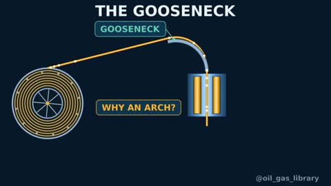
The reel, gooseneck, injector head, control cabin, and power pack: How they work together to insert and pull the pipe.
This lesson is part of the Well Intervention track (duration 9:59 min). Watch the video first, review the key points, and test your understanding with the question below.
Key Points
- 1The reel stores the tubing and maintains tension
- 2The gooseneck guides tubing into the injector
- 3The injector head pushes and pulls via gripper chains
- 4The control cabin monitors weight, depth, and pressure
Written Lesson
The Reel (Reel)
The reel stores the tubing and is driven by a hydraulic motor that maintains constant tension between the reel and the gooseneck, preventing slack during RIH and over-tension during POOH. The injector head actually moves the pipe; the reel simply follows it. The reel features a levelwind assembly for smooth, spooling layer-by-layer, a high-pressure rotating swivel at its core to allow pumping through the tubing while rotating, and an isolation valve on the pump-in line.
The Gooseneck (Gooseneck)
A curved steel arch fitted with rollers that guides the tubing from the reel to the injector head, transitioning it from a near-horizontal trajectory to vertical entry. The arch radius is engineered for the specific tubing diameter, as every bend cycles fatigue into the pipe. Thus, the gooseneck is not just a guide, but a critical factor affecting tubing fatigue life.
The Injector Head (Injector Head)
The heart of the system. It features two opposing continuous chains carrying profile-matched gripper blocks, compressed against the tubing by hydraulic rams to generate friction, and driven by hydraulic motors. The injector forces tubing down when wellhead pressure exceeds pipe weight (snubbing), and holds or pulls the pipe when weight dominates. It houses the load cell providing weight readings and the depth counter.
Clamping pressure must be sufficient to prevent slippage without deforming the pipe. The stripper assembly is mounted directly below the injector head.
Control Cabin and Data Acquisition System
From the cabin, the operator controls pipe speed, direction, gripper pressure, reel tension, stripper, and BOP functions. Screens display real-time weight, depth, pipe speed, circulation pressure, wellhead pressure, and pump rate. All operational data is recorded continuously to feed fatigue tracking models.
The Power Pack (Power Pack)
A diesel engine drives hydraulic pumps supplying power to the injector head, reel, BOP, and stripper. It includes a hydraulic accumulator system with stored energy capacity to close the BOP in the event of engine failure.
Weight indicator readings: more than just pipe weight
The indicator weight read by the operator is the net sum of several forces: buoyed pipe weight, wellhead pressure thrust pushing the tubing out through the stripper, friction from the stripper packing elements, and wall contact friction. Engineers model predicted weight profiles beforehand so operators can compare real-time values and detect sticking or buckling early.
Weight in air (lb/ft) ≈ 3.4 × steel area (in²)
Buoyancy factor = 1 − MW ÷ 65.5
Calculation example: 1.75 in tubing with 0.134 in wall thickness: cross-sectional area (π ÷ 4) × (1.75² − 1.482²) = 0.7854 × 0.866 ≈ 0.680 in², giving a weight in air ≈ 3.4 × 0.680 ≈ 2.31 lb/ft. In 8.6 ppg fluid inside and outside, buoyancy factor is 1 − 8.6 ÷ 65.5 ≈ 0.869. At 10,000 ft, weight in air is approx 23,100 lb, and buoyed weight ≈ 23,100 × 0.869 ≈ 20,070 lb, before accounting for well pressure forces and friction.
Rig-up and Rig-site Considerations
The injector head is positioned above the BOP stack using a crane or jacking frame, ensuring proper reel distance and alignment angle to the gooseneck. Every hydraulic and flow line, along with all valves, is pressure tested prior to opening the well. Equipment layout must maintain a clear, safe escape route for crew members.
Summary
- The reel stores the pipe and maintains tension; the injector head provides actual pipe movement.
- The gooseneck guides the tubing; its radius impacts pipe fatigue life.
- Indicator weight combines buoyed weight, well pressure push, and mechanical friction.
- The control cabin logs critical data used for fatigue tracking.
The figures and examples in this lesson are for educational purposes. On the job, always follow your company procedures and accredited training center instructions.
Test Yourself
Lesson Glossary
The drum on which the pipe is stored and kept under tension.
An arch that guides the pipe from the reel to the injector head.
Components on the chains that hold the pipe by friction.
A sensor measuring the force on the injector head, providing the weight reading.
Engine and pumps providing hydraulic pressure to the equipment.
Continuous length of steel tubing spooled on a reel, deployed into live wells without making pipe connections.
Pushes the CT into the well and pulls it back out using gripper chains.
Conduit through which produced fluids flow to the surface.